1. Understanding the flowchart
In simple terms, a flowchart is a diagram that describes a process. This process can be a sequence of operations, a description of the entire process from input to output of the system, or the entire process of coordinated and orderly handling of a certain matter by different personnel, organizations, or systems.
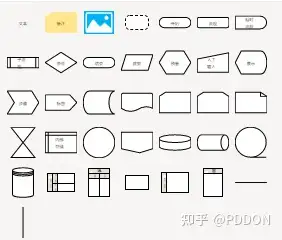
The flowchart includes the following elements
- Flowchart Component Type (Shape)
- The structure of a flowchart
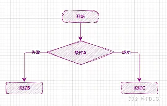
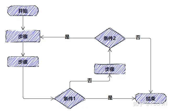
Branch structure
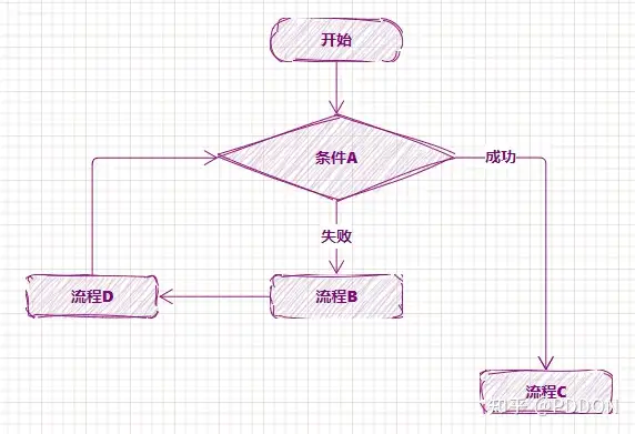
Loop Structure
- Flow direction/sequence control of flowchart
- Flowchart partitioning
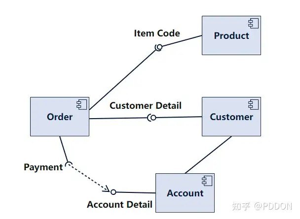
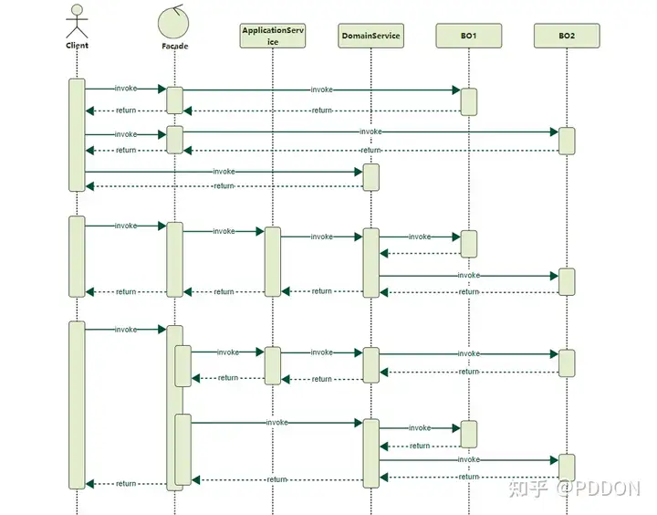
- Comparison of other similar drawings
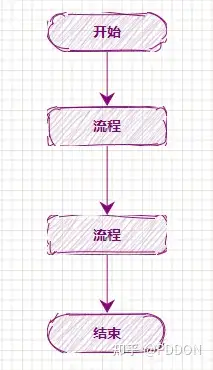
The flowchart emphasizes the description of the processing process, with its main control structures being sequence, branching, and loop, and strict sequence and time relationships between each processing process. The UML activity diagram describes the rules followed by the sequential relationships of object activities, emphasizing the behavior of the system rather than its processing.
UML activity diagrams can represent the situation of concurrent activities, while process diagrams cannot.
UML activity diagrams are object-oriented, while process diagrams are process oriented.
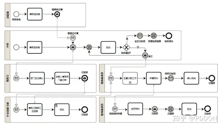
BPMN
The flow chart mainly describes for people to see. BPMN mainly describes the executable model chart, which needs to be accurately interpreted and generated by the workflow engine or business process management system, and is executable. The description is more granular, the symbols are more, and the meaning of the identification is more accurate.
2. Basic requirements for drawing a flowchart
- Please divide the complex process diagram into main and sub process diagrams to draw, and do not draw them in the same process diagram.
- The flowchart prohibits endless loops.
- The flowchart must be drawn with a single entry and a single exit feature. The 'start' symbol can only appear once, but the 'end' symbol can appear multiple times.
- The same flowchart should have consistent symbol sizes for a more aesthetically pleasing appearance.
- The order of drawing flowchart symbols should be from top to bottom and from left to right.
- On the same path, there should be only one arrow indicating the execution order of the process or the flow of data.
- If there are references to other processes in the flowchart. Defined processes can be referenced without the need for repeated drawing.
- Path symbols should avoid crossing each other.
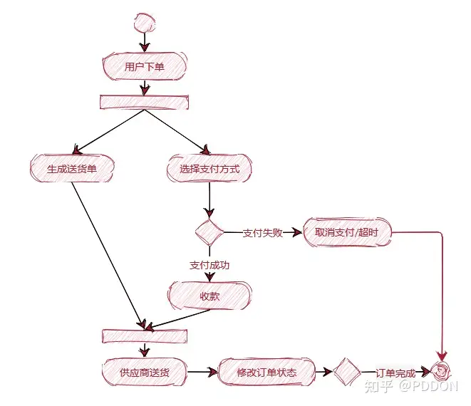
1. Common Flowchart Components
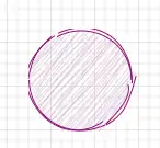
(1) This component represents the beginning and end of the process, and this icon should be marked with "Start" and "End".
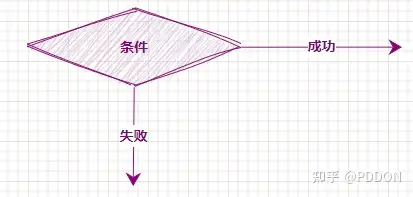
(2) Used to identify the situation of branch judgment (one out of two), especially in the case of success/failure and yes/no, it is necessary to identify the situation represented by this branch on the branch exit line. This symbol is in the box and needs to indicate the content of the judgment
(3) Invoke external data, reference external data
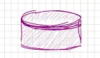
(4) Store data, output stored data
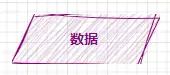
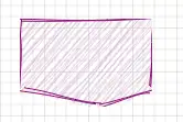
(5) Represent the documents involved in the process
https://pica.zhimg.com/80/v2-ab7b5680e1c97ffeb8ecc762eb1b214a_720w.webp?source= 1940ef5c
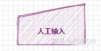
(6) Indicates manual input processing. For example, manually entering a username and password. Or manually enter data, etc.
(7) For public process processing or layout needs, if a set of processes needs to be represented by an identification symbol on this page, it can be identified through page references. Page references must be identified by a string of characters, and a specific description of the process must be provided at the same identifier elsewhere on the same page.
(8) For public process processing or layout needs, if a set of processes needs to be represented by an identifier in other pages, it can be identified through off page references (off page references). Off page references must be identified by a string of characters, and VISIO will automatically generate a separate page based on the string identification.
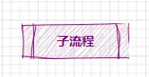
(9) Pre defined sub processes. Reference a pre-defined process for processing. For example, the sub process of automotive air conditioning processing.
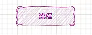
(10) Process steps/operations
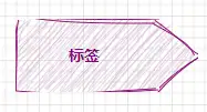
(11) Label
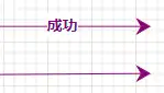
(12) Process flow relationship and direction description
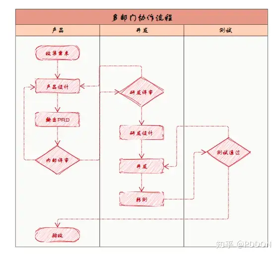
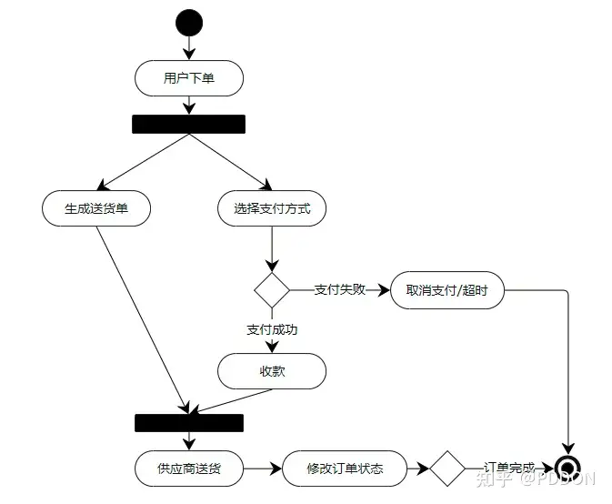
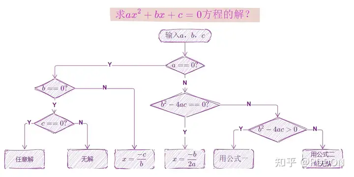
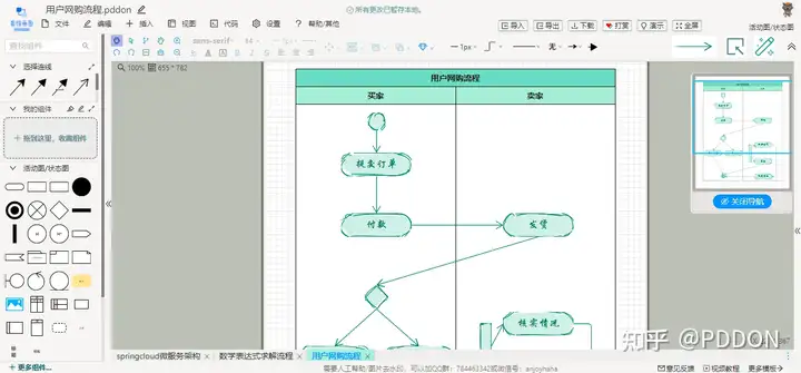
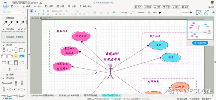
3. Drawing Example
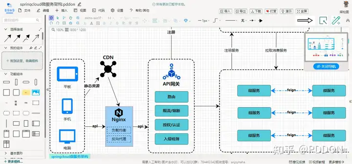
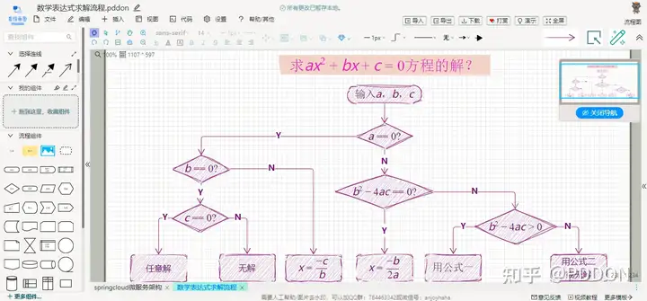
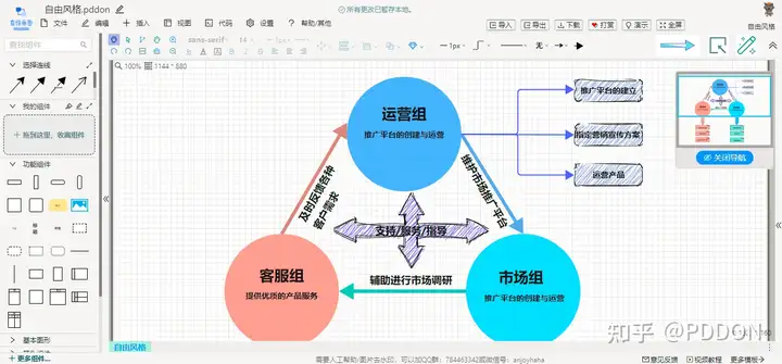
As the author of PDDON online drawing and the only completely free commercial grade drawing software on the market, we welcome everyone to use it for free. The following drawings are all drawn using PDDON. Please remember to like and collect them!
Drawing workspace

4. Summary
If you need to draw a good flowchart, the basic knowledge points and usage skills of this article also need to be carefully studied by the flowchart expert. I believe that through the study of this article, drawing an excellent flowchart can bring you more benefits.
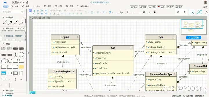
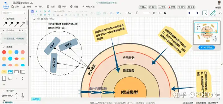
PDDDON supports not only the drawing of flow charts, but also UML modeling, flow charts, mind maps, database model diagrams, fishbone diagrams, Wayne diagrams, BPMN, network topology diagrams, free style drawings, and a series of drawings. Pay attention to PDDON's online drawing official account, and don't worry about finding a good drawing tool any more.
PDDON statement: The provided drawing function is free of charge and everyone is welcome to use it for free.
Friends who like it can follow me and regularly share drawing tutorials and templates.
Friends who think it's good can like, like, and bookmark it. Thank you all.
PDDON online drawing site addr: pddon.com